AIR PREHEATER
Introduction on Air preheater
An air preheater (APH)
is any device designed to heat air before another process (for
example, combustion in a boiler) with the primary objective of increasing
the thermal efficiency of the process. They may be used alone or to replace
a recuperative heat system or to replace a steam coil.
In
particular, this article describes the combustion air preheaters used in
large boilers found in thermal power stations producing electric
power from e.g. fossil fuels, biomass or waste. For
instance, as the Ljungström air preheater has been attributed worldwide fuel
savings estimated to
4,960,000,000 tons of oil, "few inventions have been
as successful in saving fuel as the Ljungström Air Preheater", marked as
the 44th International
Historic Mechanical Engineering Landmark by the American Society of Mechanical
Engineers.
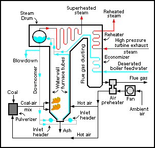
The
purpose of the air preheater is to recover the heat from the boiler flue
gas which increases the thermal
efficiency of the boiler by reducing the useful heat lost in the flue gas. As a
consequence, the flue gases are also conveyed to the flue
gas stack (or chimney) at a lower temperature, allowing the simplified
design of the conveyance system and the flue gas stack. It also allows control
over the temperature of gases leaving the stack (to meet emissions regulations,
for example). It is installed between the economizer and chimney.
Advantages of
Using Air Heater
The recovery of waste heat from the flue gas and
heating the air required for Boiler In an air heater gives the following
advantages.
a) The
Boiler efficiency is increased.
b) More
stable combustion in the furnace.
c) The
combustion is intensified with the use of hot air.
d) Lower grades of coals can be burnt efficiently with hot-air.
e) The use of hot air improves the heat
transfer rate and so less heat transfer area will be required.
f) The combustion is made complete with negligible amount of carbon
in ash.
g) Faster
load variations are possible.
h) The coal can be dried effectively for easy pulverization and
combustion.
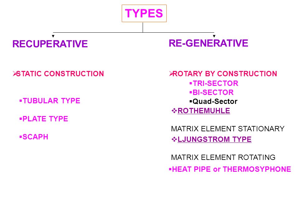
Types of air preheaters
1.
Recuperative Type Air Preheater
Ø Horizontal Type Air Preheater
Ø Vertical Type Air Preheater
2. Regenerative Type Air Preheater
Ø Bi-Sector Type - with Single Gas and Air Stream
Ø Tri-Sector Type- with Single Gas Stream but two air streams (Primary Air
Stream and Secondary Air Stream)
Ø Quad-Sector Type- with Single Gas Stream - One Primary Air Stream
sandwiched between two Secondary Air Streams for Leakage reduction.
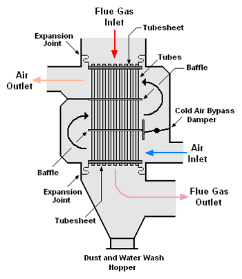
Tubular type Air preheater
Construction
features
Tubular preheaters consist of straight tube bundles which pass through the outlet ducting of the boiler and
open at each end outside of the ducting. Inside the ducting, the hot furnace
gases pass around the preheater tubes, transferring heat from the exhaust gas
to the air inside the preheater. Ambient air is forced by a fan through ducting
at one end of the preheater tubes and at other ends the heated air from inside
of the tubes emerges into another set of ducting, which carries it to the
boiler furnace for combustion.
Problems
The tubular preheater ducting’s for cold and hot air require more space
and structural supports than a rotating preheater design. Further, due to dust-laden
abrasive flue gases, the tubes outside the ducting wear out faster on the side
facing the gas current. Many advances have been made to eliminate this problem
such as the use of ceramic and hardened steel.
Many new circulating
fluidized bed (CFB) and bubbling
fluidized bed (BFB) steam generators
are currently incorporating tubular air heaters offering an advantage with
regards to the moving parts of a rotary type.
Dew point
corrosion
Dew point corrosion occurs for a variety of
reasons. The type of fuel used, its sulphur content and moisture content
are contributing factors. However, by far the most significant factor in dew
point corrosion is the metal temperature of the tubes. If the metal temperature
within the tubes drops below the acid saturation temperature, usually at
between 190 °F (88 °C) and 230 °F
(110 °C), but sometimes at
temperatures as high as 260 °F (127 °C), then the risk of dew point corrosion damage becomes considerable.
ADVANTAGES OF RECUPERATIVE AIR
HEATER
The major advantage is that this type of air heater
is not having any moving parts. So, the maintenance involved is less and so no
auxiliary power consumption.
Also, there is no possibility
of fly ash carryover by the heated air in these air heaters.
DISADVANTAGES OF RECUPERATIVE
AIR HEATER
a)As the heat transfer areas are made of tubes or plates the air
heater occupies more area. Also, it involves more material cost.
b) Any puncture in tubes results in leaking of air into the flue gas
stream thereby increasing the load on fans.
c)Deposits
on the tube, surface reduces the heat transfer.
d) A pressure drop of flue gas across the air heater is high.
e)The cross-flow heat transfer in the tubular air heater is less
efficient.
f)Severely
affected due to cold end corrosion.
g)Replacement of punctured tubes is a major task requiring more
downtime on the boiler.
With the number of
disadvantages, the use of recuperative air heaters in large capacity boilers is
becoming unpopular. However, in certain boilers, the tubular air heater is used
to separately heat the primary air to avoid carryover of fly ash to pulverize.
Regenerative
air preheaters
There are two types of regenerative air preheaters: the rotating-plate
regenerative air preheaters (RAPH) and the stationary-plate regenerative air
preheaters (Rothemuhle).
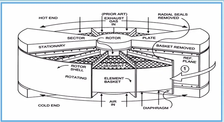
Rotating-plate
regenerative air preheater
The rotating-plate design
(RAPH) consists of a central rotating-plate element installed within a
casing that is divided into two (bi-sector type),
three (tri-sector type)
or four (quad-sector type) sectors containing seals around the element.
The seals allow the element to rotate through all the sectors, but keep gas
leakage between sectors to a minimum while providing separate gas air and flue gas paths through each sector.
Tri-sector types
are the most common in modern power generation facilities. In the tri-sector
design, the largest sector (usually spanning about half the cross-section of
the casing) is connected to the boiler hot gas outlet. The hot exhaust gas
flows over the central element, transferring some of its heat to the element,
and is then ducted away for further treatment in dust collectors and other equipment before being
expelled from the flue gas stack. The second, smaller sector is fed with
ambient air by a fan, which passes over the heated element as it rotates into
the sector, and is heated before being carried to the boiler furnace for
combustion. The third sector is the smallest one and it heats air which is
routed into the pulverize sand used to carry the coal-air mixture to coal
boiler burners. Thus, the total air heated in the RAPH provides: heating air to
remove the moisture from the pulverized coal dust, carrier air for transporting
the pulverized coal to the boiler burners and the primary air for combustion.
The rotor itself is the medium of heat transfer in this system and is usually composed
of some form of steel and/or ceramic structure. It rotates quite slowly
(around 1-2 RPM) to allow optimum heat transfer first from
the hot exhaust gases to the element, then as it rotates, from the element to
the cooler air in the other sectors.


Construction features
In this design the whole air
preheater casing is supported on the boiler supporting structure itself with
necessary expansion joints in the ducting.
The vertical rotor is supported
on thrust bearings at the lower end and has an oil bath lubrication, cooled by
water circulating in coils inside the oil bath. This arrangement is for cooling
the lower end of the shaft, as this end of the vertical rotor is on the hot end
of the ducting. The top end of the rotor has a simple roller bearing to hold
the shaft in a vertical position.
The rotor is built upon the
vertical shaft with radial supports and cages for holding the baskets in
position. Radial and circumferential seal plates are also provided to avoid
leakages of gases or air between the sectors or between the duct and the casing
while in rotation.
For on line cleaning of the
deposits from the baskets steam jets are provided such that the blown-out dust
and ash are collected at the bottom ash hopper of the air preheater. This dust
hopper is connected for emptying along with the main dust hoppers of the dust
collectors.
The rotor is turned by an air
driven motor and gearing, and is required to be started before starting the
boiler and also to be kept in rotation for some time after the boiler is
stopped, to avoid uneven expansion and contraction resulting in warping or
cracking of the rotor. The station air is generally totally dry (dry air is
required for the instrumentation), so the air used to drive the rotor is
injected with oil to lubricate the air motor.
Safety protected inspection
windows are provided for viewing the preheater's internal operation under all
operating conditions.
The baskets are in the sector
housings provided on the rotor and are renewable. The life of the baskets
depends on the ash abrasiveness and corrosiveness of the boiler outlet gases.
Problems
The boiler flue gas contains many
dust particles (due to high ash content) not contributing towards combustion,
such as silica, which causes abrasive wear of the baskets, and may also contain
corrosive gases depending on the composition of the fuel. For example, Indian coals
generally result in high levels of ash and silica in the flue gas. The wear of the
baskets, therefore, is generally more than other, cleaner-burning fuels.
In this RAPH, the dust-laden,
corrosive boiler gases have to pass between the elements of air preheater
baskets. The elements are made up of zig-zag corrugated plates pressed into a
steel basket giving sufficient annular space in between for the gas to pass
through. These plates are corrugated to give more surface area for the heat to
be absorbed and also to give it the rigidity for stacking them into the
baskets. Hence frequent replacements are called for and new baskets are always
kept ready. In the early days, Cor-ten steel was being used for the elements.
Today due to technological advance many manufacturers may use their own
patents. Some manufacturers supply different materials for the use of the
elements to lengthen the life of the baskets.
In certain cases, the unburnt
deposits may occur on the air preheater elements causing it to catch fire
during normal operations of the boiler, giving rise to explosions inside the
air preheater. Sometimes mild explosions may be detected in the control room by variations in the inlet and outlet
temperatures of the combustion air.


Components of Air preheater
The air heater will consist of the following major
components.
Ø Rotor
Ø Bearing
Ø Housing
Ø Connecting Plates
Ø Sealing arrangement
Ø Drive Units
Ø Cleaning Devices
Ø Safety Devices
ROTOR
This is the heart of the
equipment resembling a solid cylinder with the extended Shafts containing the
heating elements. In the conventional air heaters (Fig. 6.3 and 6.4) the rotor
will have a hub or rotor post at the center and a shell that is connected to
the rotor post by a number of radial or diaphragm plates. These plates divide the
rotor into a number of sectors and these sectors are further divided into
compartments division plants. The heating element baskets are packed into these
compartments. A pin rack is located around the outside of the rotor to allow it
to be rotated by the drive mechanism.
In the modular type (Fig6.5
and 6.6) modules filled with heat transfer profiles inside them an: pin racks
fixed on the peripheral are suitably assembled to the rotor post to form the
rotor.
ROTOR POST
This is a cylindrical shell with two end plates
welded to it. At both ends grunion will
be connected to serve the purposes of the shaft and to accommodate the bearings
on them. The end plates otherwise called headers will support the modules that
are to be assembled to them. The top header will have a number of holes on its peripheral
edge to get assembled modules through the lug plates and IL, tension pins. The
bottom header will support the modules through the horizontal locating pins.
MODULES (Baskets)
Modules are nothing but cylindrical
segments made out of two diaphragm plates and one shed plated (Division Plate). The diaphragm plates will be stayed with the cross
plates to maintain their shapes. Inside these modules heat transfer profiles of
sufficient area are packed. The outer shell will be mounted with pin racks for
the engagement of drive units. At the extreme edges of these segments lug
plates are provided to get assembled the modules to the rotor post to form a
rotor.
Modular design is a new
concept and has its own advantages. This, in fact, reduces the erection time
considerably and improves the quality of erection besides avoiding the transit
damages. Further, it also reduces the storage spaces and makes them easier to
get stored. Also, the modules erection does not call for any welding work and
it is just enough if we assemble them with the fasteners.
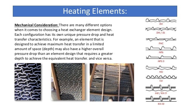
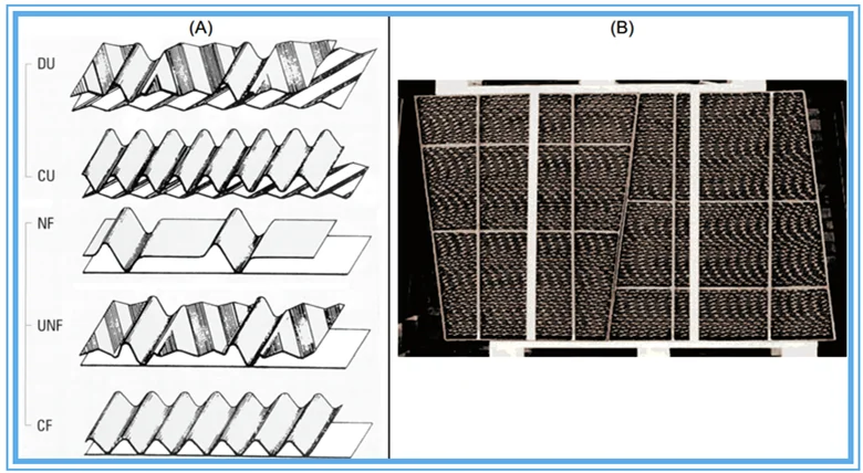
HEATING ELEMENTS
The heating elements parted
into reversible containers called baskets are placed in the rotor three tiers,
hot, intermediate and cold. The heating elements in hot end and intermediate
layer are having a profile called Double Undulated (DU) as in Fig 6.7. They are made of carbon steel.

BEARINGS
Both the extended end of the
rotor post is mounted with bearing assembly. The bearings are of spherical
roller types to take care of even slightest axial shift if takes place. The
bearing at the cold end is called as support bearing and at the hot end is
guide bearing. These bearings are housed inside the fabricated bearing housing
with the oil pump inside.
To dissipate them and there the heat generated in
the bearing assembly lubricating oil circulation units with the necessary heat
exchangers are provided separately for each bearing.
HOUSING
The housing is mode of a
number of panels and are assembled at site to form the housing to accommodate
the rotor inside. They are of two types; one is the main pedestal and the other
is the side pedestal. These pedestals are erected on the expansion plates that
are mounted on the support steels. The expansion plates make way for the
housing panels to move or their expansion due to temperature gradient. These
pedestals are load carrying members and they transmit the entire weight of air
preheater to the structural members.
CONNECTING PLATES
The connecting plates at the
hot and cold ends connect the air heater to the gas and air ducts. They mainly consist
of centre section to house the bearings and sector plates for providing scaling
between the air and gas stream. Further these forms the bifurcation for the gas
and air streams and maintain the structural rigidity by connecting the hanger
plates of the main pedestal.
SEALING ARRANGEMENT
It is an implied requirement
that the rotating parts should have some working clearance between their static
parts to avoid any interference between them. Here, in Air preheaters, rotors
are constructed to have higher clearances to take care of their thermal
expansion and these gaps are closed with the flexible seal leaves.
These seals are
classified into the following three
major types.
vRadial seals
vAxial Seals
vBypass seals
The main purpose of these
seals is to reduce the leakage between the gas and air circumferential
direction respectively.
Of late automatic leakage
control systems (ALCS) have been introduced to reduce the leakage that can
occur due to the thermal deformation of the rotors. By adjusting the sector
plates through mechanical ejaculators to closely follow the shape -of the
deformed diaphragm plate the leakage reductions are achieved. With this system
the leakage can be brought down to the acceptable level.
DRIVE UNITS
The drive mechanism consists
of an electric motor connected to a gear reduction unit through a pinion. The
pinion meshes with a pin rack on the rotor which allows the rotor to rotate at
a slow speed. Air motor/DC motor is also provided to the drive arrangement
which will drive the rotor in emergencies like electric motor failure. Hand
cranking is provided for uniform cooling after tripping in case air motor/ DC
motor also fail.
CLEANING DEVICE
The heat transfer matrix
should be kept in a clean state to avoid the increase in fouling potentials and
aerodynamic resistance. Also, any unburnt fuel deposits on these matrixes may
lead to a fire. So, an on-load cleaning facility by steam soot blowing is
provided in the air preheater to clean the heat transfer matrix during the
operation itself.
By any means if the deposits
are on the high side, an off-load cleaning can be affected with the water
washing nozzle through which high pressure water can be injected.
SAFETY DEVICES
ROTOR STOPPAGE
ALARM
By any means, if the rotor
stops or slows down, there comes to the rescue of the air preheater a rotor
stoppage alarm. Equally spaced proximity switch, which in turn twin strider the
timers, inside the rotor stoppage alarm, and timing out of any of these times
will give both audio and visual alarm.
FIRE SENSING DEVICE
There are two types of fire
sensing device; one is the thermocouple type and the other is the infra-red
detecting system.
THERMOCOUPLE TYPE
A number of thermocouple
Junctions are exposed to air and gas stream, and their outputs are continuously
compared with the present value. If any variations are noticed triggering of
alarm will take place to indicate the probabilities of fire.
INFRA RED DETECTION SYSTEM
This infrared detecting system
works on the principle that by finding the level of the infrared radiation
emitted by the hot sources. The firing potential could be ascertained. These
sophisticated systems right now are imported and are quite expensive. For our
type of operations, it is felt that the thermocouple type itself is sufficient.
FIRE FIGHTING EQUIPMENT
If at all fire takes place
then the deluge system provided in the air preheater will come to the rescue.
Through the number of nozzles provided in the manifolds high volume, medium
pressure water can be flooded. Among the various alternatives this arrangement
seems to be the best from the experience of air preheater field engineers. Only
thing water in sufficient quantity should be made to flood the firing zone.
APH performance
Various seals such as radial seals, axial seals,
circumferential seals etc are provided
to prevent this leakage as leakage reduces the efficiency of air-
preheater.
2) GSE (Gas side efficiency): it is
defined as the ratio of gas temperature drop across the air-preheater to the
temperature head. Where:
Gas Temperature drop= Tin (flue gas)-Tout (Flue
gas)
Temperature head=Tin
(Flue gas)-Tin(air)
3) X-Ratio: it is defined as the ratio of heat
capacity of air passing through the air-preheater to the
heat capacity of flue gas passing
through the air-preheater. X-Ratio is dependent upon moisture in
coal, air infiltration, air and gas
mass flow rates; leakage through the APH; specific heats of air and flue gas.
4) Pressure drop: it refers to the
change in the pressure of both air and flue gas as these passes through
the APH. Low pressure drop is preferred
for better performance of an air-preheater.
5) Temperature drop of flue gas: there
is a decrease in temperature of flue gas as it transfers the heat
to the heating elements of the
air-preheater.
6) Temperature rise of air: as the air
being transferred to the boiler comes in contact with the heating
elements, the temperature rises as the
elements are at a high temperature when compared to in coming
air.
Ljungström air preheater
Ljungström air preheater is an air
preheater invented by the Swedish engineer Fredrik Ljungström (1875-1964). The patent was
achieved in 1930.
Even in a modern utility boiler provides up to 20 percent of the
total heat transfer in the boiler process, but only represents 2 percent of the
investment.
The factory and workshop activities and laboratories in Lidingö
would remain throughout the 1920s, with some 70 personnel. In the 1930s it was
used a film studio, and was finally demolished in the 1970s to give space for
new industry premises.
With Fredrik Ljungström's technology of the air preheater
implemented in a vast amount of modern power stations around the world until this
day with total attributed worldwide fuel savings estimated to
4,960,000,000 tons of oil,
"few inventions have been as successful in saving fuel as the Ljungström
Air Preheater".
In 1995, the Ljungström air preheater was distinguished as the
44th International
Historic Mechanical Engineering Landmark by
the American Society of Mechanical
Engineers.
Comments
Post a Comment